Self Exciting Alternator Wiring Diagram
According to earlier, the lines at a alternator exciter wiring diagram signifies wires. It includes guidelines and diagrams for different kinds of wiring techniques and other products like lights, windows, etc.
Some gm vehicles have the alternator check light bulb from the factory.

Self exciting alternator wiring diagram. This particular model (10si, used in the s and early 80s) is the one. In this video , i will teach you how to use a simple diode for the self excitation of a 12v 90 ampere car alternator and thus using it as a generator. Everything charges great and has for a couple years now.
If you buy any other plug, you will need to add a 470 ohm 1/2 watt resistor to the l wire. Wiring diagram contains several detailed illustrations that display the connection of assorted things. One wire alternator wiring diagram ford.
Common delco si series alternator wiring diagram. But it does not mean connection between the. Two wire means that you use the main battery wire to the back of the alternator and also ignition wire to the #1 terminal to activate the alternator.
Wiring diagram contains several detailed illustrations that display the connection of assorted things. Higginbotham on saturday february 9th 2019. Depending upon the maximum output of the alternator, use the following chart as a minimum wire size guide.
I drilled a hole.the dr44g gmc alternator is a amp alternator. This type of alternator requires only the positive and negative battery cables. Sometimes, the wires will cross.
We are commonly asked how to wire the delco si series alternators upon maintenance or upgrading from an older generator. With this setup the alternator. Wire size is based on 4’ battery cables.
While this series of unit often runs as a self exciting one wire, agricultural applications also used 3 wire connections to the alternator. By david smith sep 22, 2016. One wire alternators self exciting or “one wire” alternators will have no plug on the alternator whatsoever, and the oem alternator harness plug will be left disconnected.
Anyway.i have a self exciting 3g alternator in my 65 mustang. It is very important to use the correct wire size to connect the alternator to the battery. Injunction of two wires is usually indicated by black dot on the intersection of two lines.
Dr44 alternator wiring to gbody lsx, mod motor and gen iii hemi what you are looking for is a dr44g. But, it does not mean connection between the wires. Two wire means that you use the main battery wire to the back of the alternator and also ignition wire to the #1 terminal to activate the alternator.
The large batt terminal which gets connected to your battery.replacing a 20dn, 30dn, 41 dn, and d.c. There’ll be primary lines which are represented by l1, l2, l3, and so on. Print the wiring diagram off plus use highlighters to trace the signal.
I never feel more stupid than when i'm trying to figure out a wiring issue.so i apologize in advance since i know this has been asked a ton of times. A dr44/dr44g alternator mounted in your vehicle. 2 wire alternator wiring diagram 2 wire alternator wiring diagram ac delco 2 wire alternator wiring diagram bosch 2 wire alternator wiring diagram every electric arrangement is made up of various distinct pieces.
Higginbotham on friday, february 15th, 2019 in category wiring diagram. The alternator turns on the voltage regulator when the engine starts turning the alternator. Two wire means that you use the main battery wire to the back of the alternator and also ignition wire to the #1 terminal to activate the alternator.
The alternator turns on the voltage regulator when the engine starts turning the alternator. All of the wiring diagrams i have seen have a wire from + through hook the #1 alternator terminal to acc and the tractor coil power to ign. 1 wire alternator diagram carlplant size.
Inspect the back and sides of the. Al17f4 alternator wiring diagram al17f4 alternator wiring diagram while this series of unit often runs as a self exciting one wire, agricultural applications also used 3 wire connections to the alternator. The 10si has three terminals (including those with a 1 wire regulator).
A wire size too small can allow the wire to overheat, melt the insulation and cause a fire or worse. It includes guidelines and diagrams for different kinds of wiring techniques and other products like lights, windows, etc. (si and si series are identical except stator is a delta.).
All those extra wires are unused pins in the connector for future expansion. The alternator turns on the voltage regulator when the engine starts turning the alternator. 1 trick that we 2 to printing a similar wiring plan off twice.with this kind of an illustrative guidebook youll have the ability to.
I searched through old topics and couldn't find an answer. By admin october 22 2017.
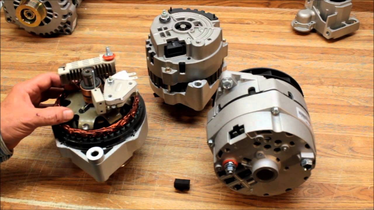
Basic Gm Alternator Wiring Best Wiring Library Gm 1 Wire Alternator Wiring Diagram Wiring
Delco Remy 10si Wiring Diagram
Common Delco SI Series Alternator Wiring Diagram Smith Co Electric
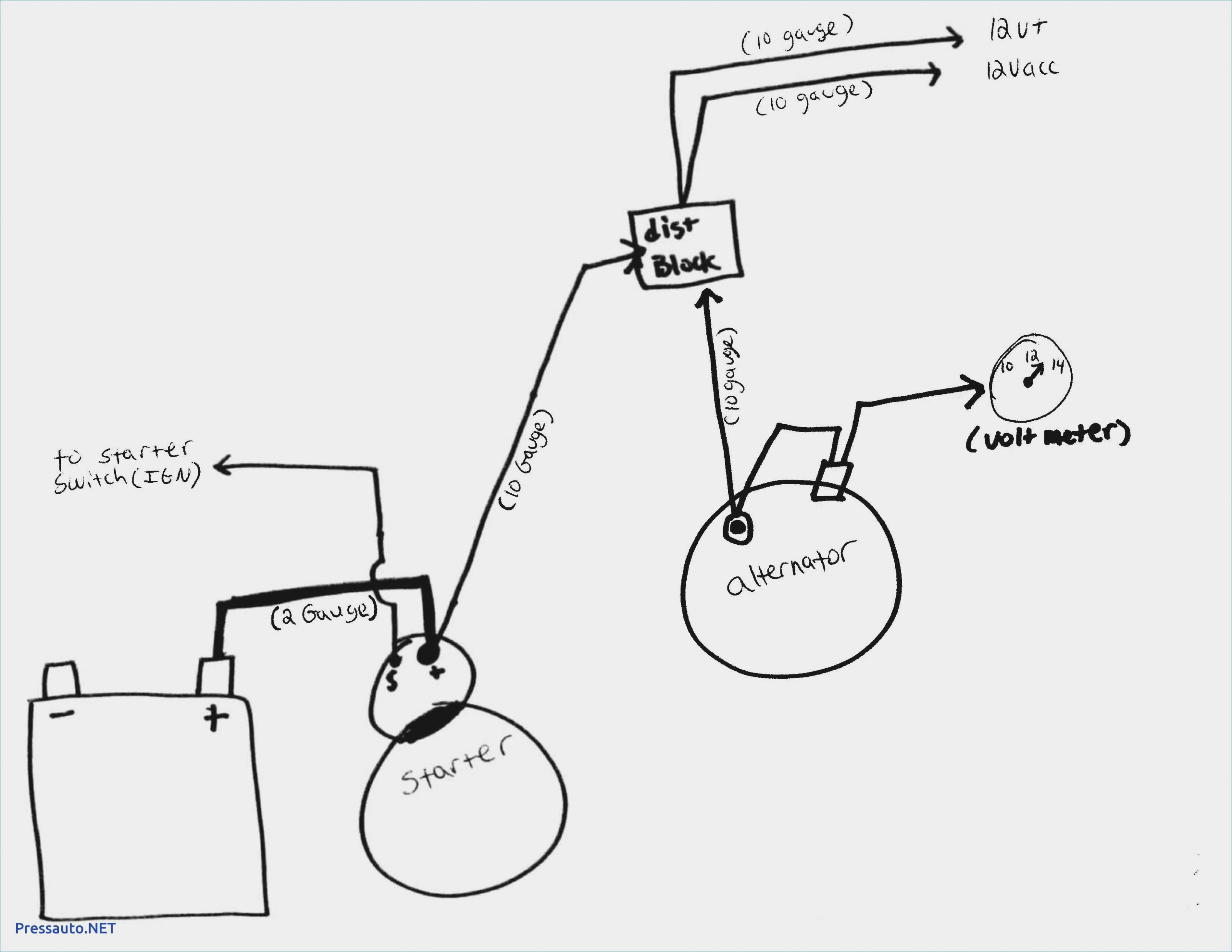
Gm 1 Wire Alternator Wiring Diagram Cadician's Blog

12v 90 Amps Car Alternator to Self Excited Generator using DIODE in 2020 Alternator, Car
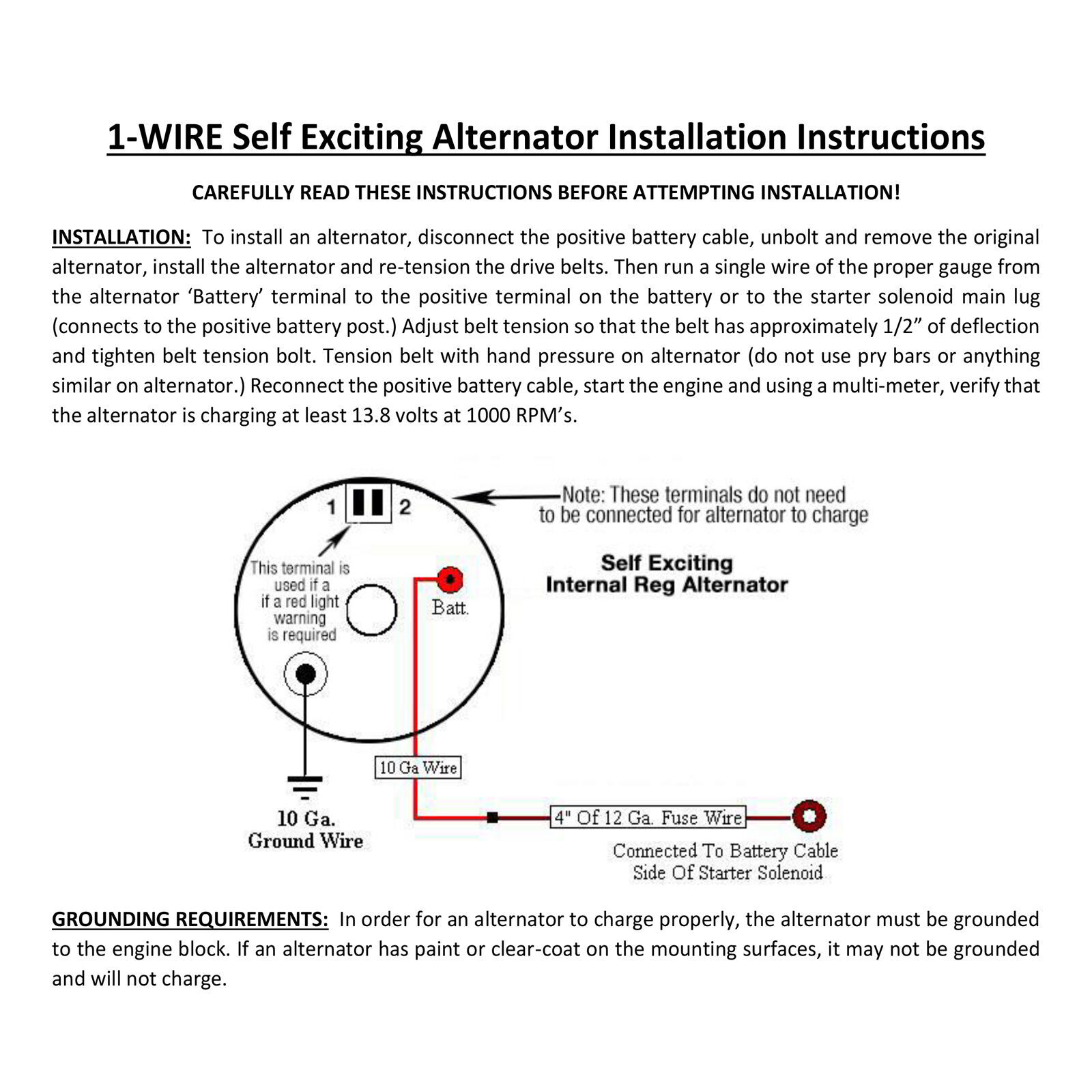
Self Exciting Alternator Wiring Diagram 1
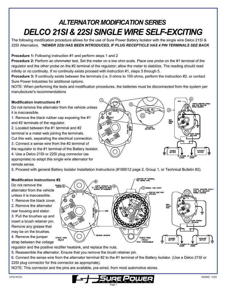
DELCO 21SI & 22SI SINGLE WIRE SELFEXCITING ALTERNATOR MODIFICATION SERIES
Single Wire Alternator Wiring Diagram

Self Exciting Alternator Wiring Diagram Collection Wiring Diagram Sample
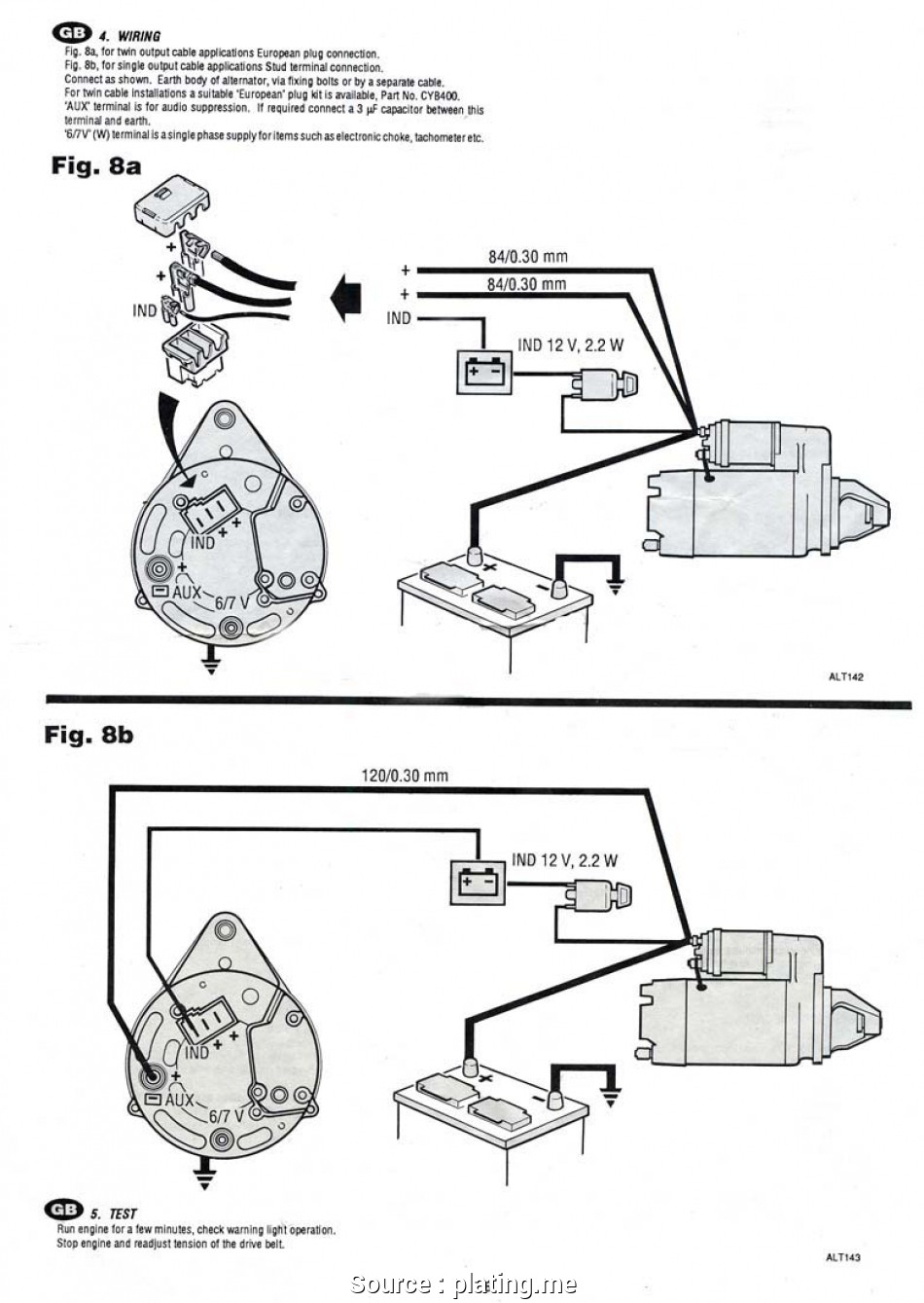
How To Excite The One Wire Self Exciting Alternator. Youtube Alternator Exciter Wiring
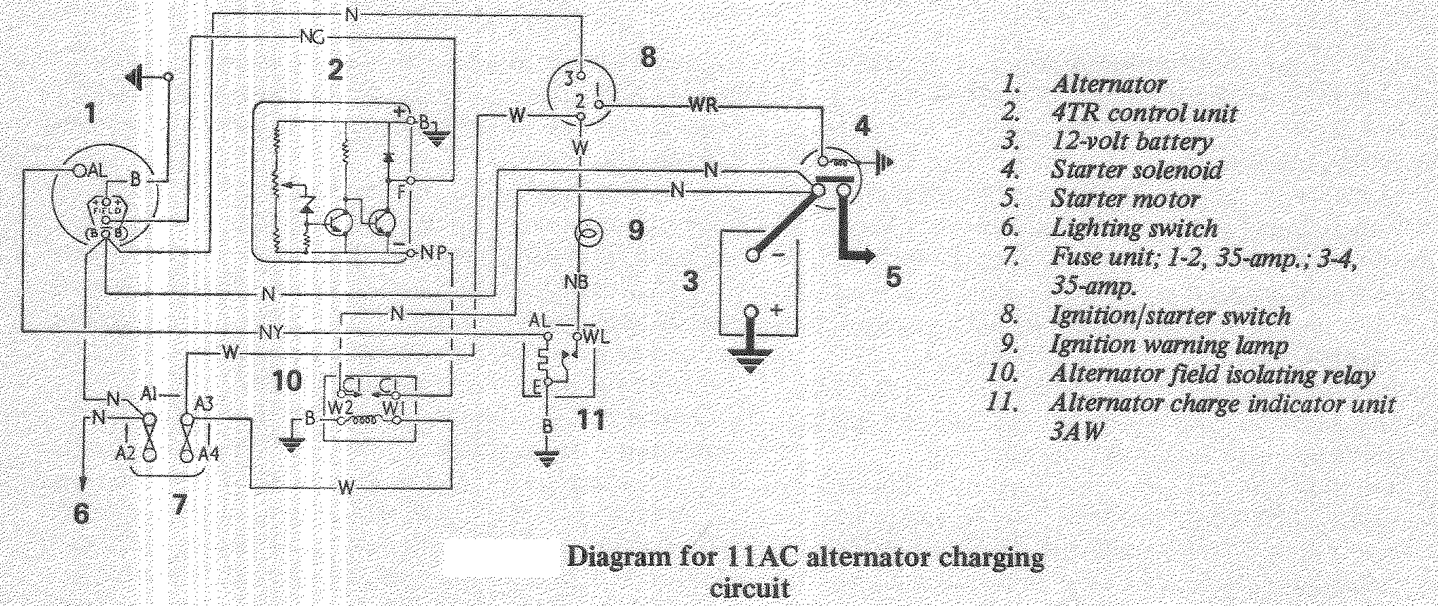
Self Exciting Alternator Wiring Diagram Collection Wiring Diagram Sample
Delco 10si Alternator Wiring Diagram

Self Exciting Alternator Wiring Diagram Collection Wiring Diagram Sample
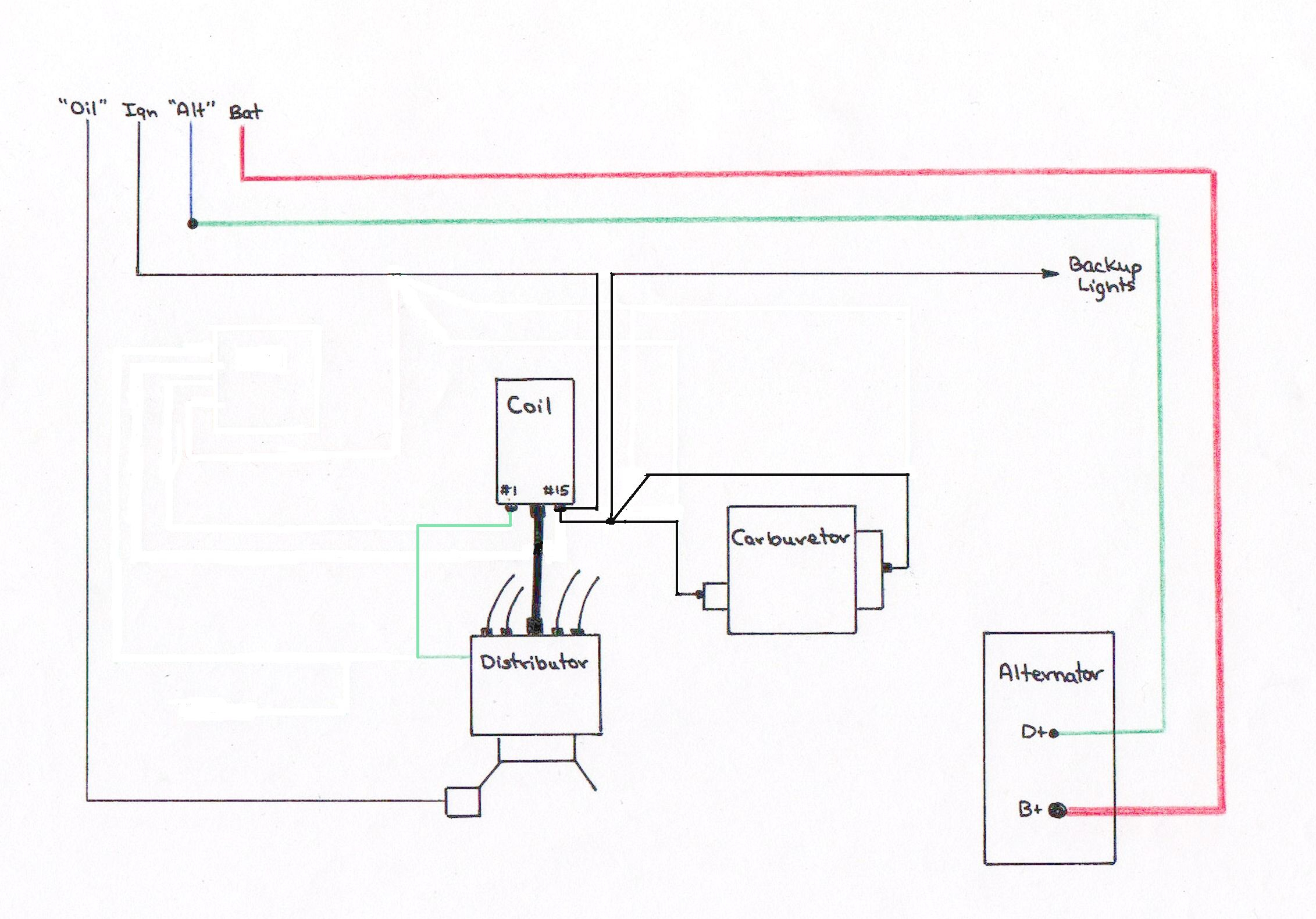
Microcontroller How To Monitor An Alternator Exciter Wire With Mcu Alternator Exciter Wiring
Wiring Diagram For Alternator With Internal Regulator
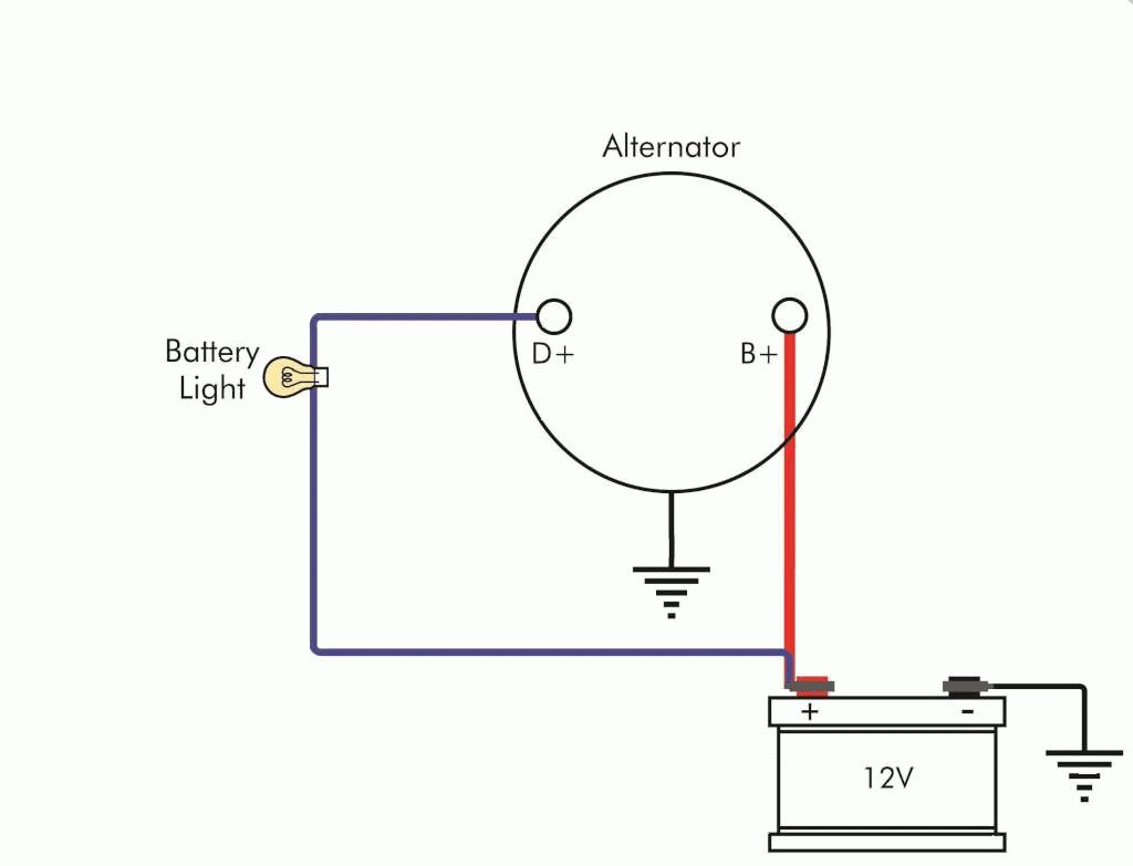
Microcontroller How To Monitor An Alternator Exciter Wire With Mcu Alternator Exciter Wiring
Self Exciting Alternator Wiring Diagram Collection Wiring Diagram Sample


